

A customer looks at a profile and says: "there's a scratch on this."
Production looks at the same line and says: "that's just a die line, it's normal."
Quality looks at it and says: "it depends on the surface requirement."
Quality is giving the technically correct answer — because the real question was never "is there a die line?" It's "does this die line fall within the agreed surface-quality requirement for this specific application?" Those are very different questions, and mixing them up is one of the most common sources of customer-extruder disputes in the industry.
1. What Exactly Is a Die Line?
The Aluminum Association's widely referenced definition describes die lines as longitudinal depressions or protrusions that form on the surface of extruded (or drawn) material because of imperfections on the die surface.
A simple mental model: imagine pushing soft clay through a shaped opening. If that opening has one tiny rough spot or a damaged area, that spot continuously marks the clay as it passes through — leaving one line running the full length of whatever comes out. Real aluminium extrusion involves far more complex metallurgical and tribological behaviour, but the basic geometric idea is the same: a local condition at the die bearing can repeatedly influence the identical position on the profile.
That's why a genuine die line almost always runs parallel to the extrusion direction and tends to stay at approximately the same position on the profile cross-section, length after length.
One useful detail often missed: even with a well-designed, correctly-extruded process — optimum bearing length, correct temperature, a properly polished die land — very fine, shallow die lines can still occur. These are sometimes called micro die lines, and they're a normal characteristic of the process rather than evidence that something went wrong.
2. Why Do Die Lines Form?
It's more complicated than just "the die is rough." Five mechanisms are worth understanding:
a) An imperfection on the die bearing
The bearing is the final surface controlling metal flow before exit. A small polishing mark, local roughness, minor damage, a sharp irregularity, adhered aluminium, or debris at one point on the bearing gets passed by hot aluminium continuously — producing one steady longitudinal line.
b) Aluminium adhesion to the bearing
This is a critical mechanism. Aluminium isn't simply sliding smoothly through the die — there's severe pressure, deformation, heat and surface interaction at play. A small amount of aluminium can adhere to the die land, and further metal interacts with that adhered material as it flows past. The local surface condition changes as a result, and depending on severity, this can progress from a fine die line into pickup, scoring, or general roughness.
c) Die bearing damage or deterioration over time
A newly polished bearing can produce an excellent surface — but dies work under severe operating conditions, and bearing condition changes over repeated cycles: wear, local damage, deterioration of a nitrided layer, imperfect die correction, and gradual aluminium adhesion buildup are all possibilities.
d) Extrusion temperature and speed
Higher speed and unfavourable temperature can intensify surface interaction and adhesion at the aluminium-die interface. This is why operators sometimes see a clean surface at a lower speed, watch die lines or pickup appear as speed increases, and see the surface improve again once speed is brought back down. That's not inconsistency in the die — it's the process window shifting.
e) Billet quality and homogenisation
Not every die line problem starts in the die shop. Inclusions, intermetallic particles, or inadequate homogenisation in the billet can disturb the die surface on contact, and that disturbed location then continuously marks every length extruded afterward:
Billet-related particle → bearing disturbance → continuous longitudinal line on the profile.
The visible defect shows up on the extrusion — but the root cause may have started upstream, in the billet.
3. Are All Longitudinal Lines Die Lines?
No — and this is where a lot of defect analysis goes wrong from the start. A line running along an extrusion could be a die line, pickup, scoring, a scratch, a streak, a weld-related mark, or simple handling damage. These terms are not interchangeable.
| Feature | Typical pattern | Most likely source |
|---|---|---|
| Die line | Continuous, longitudinal, stable position | Fixed die bearing imperfection |
| Pickup | Intermittent short scoring, may include aluminium deposits | Aluminium periodically sticking/breaking from bearing |
| Scratch | Starts/stops suddenly, may cross extrusion direction, random position | Handling or mechanical contact after die exit |
| Streak | Gloss/colour variation, often not a physical groove | Microstructure or etching-response variation, especially after anodizing |
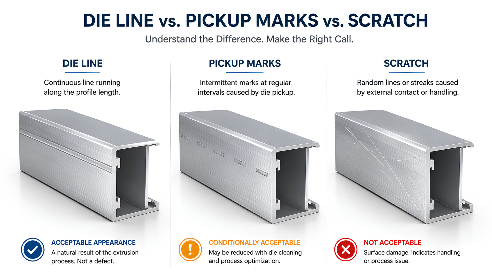
A useful practical test for die line vs. handling damage: does the line stay at exactly the same position relative to the profile geometry — always 8 mm from an edge, always beside the same rib, present on consecutive lengths? That strongly points to a process or die source. A mark that starts and stops randomly, changes position between pieces, or crosses the extrusion direction is more consistent with handling damage. This is a diagnostic rule of thumb, not an absolute definition.
The die line vs. streak distinction matters especially for anodized profiles. Streaking is often primarily an optical or metallurgical effect — microstructure variation and uneven chemical etching response can create a visible gloss or colour difference even without a physical groove. But the two can interact: a pronounced die line can also contribute to an apparent streaked appearance after anodizing, which is why people sometimes say "the line appeared after anodizing" — in reality, the line often existed before anodizing, and the finishing process simply made it more visible.
4. The Most Important Question: Are Die Lines Always a Defect?
No — and this deserves careful explanation, because it's the crux of most disputes.
Extrusion inherently produces a mill-finish surface. The profile has passed through a steel die under extreme pressure and temperature. Expecting every mill-finish extrusion to look like mirror-polished stainless steel is unrealistic unless additional surface processing and requirements have specifically been agreed.
There's a genuine spectrum here — from normal extrusion appearance (fine, uniform longitudinal texture that's characteristic of the process itself) to an actual surface defect (a pronounced groove, protrusion, scoring mark, or cluster of lines that exceeds the required surface quality for that part).
Three profiles, three outcomes
| Application | Surface observed | Likely acceptance |
|---|---|---|
| Hidden structural support | Fine longitudinal lines, no deep groove, never visible after install | Likely acceptable, subject to spec |
| Powder-coated window frame | Minor die lines on mill finish, uniform after coating | May be acceptable |
| Premium clear-anodized architectural face | Strong continuous line on exposed face, visible after anodizing | Potentially unacceptable |
Same manufacturing process. Same underlying defect type. Three completely different acceptance decisions — because the application and the exposed surface changed each time. Anodizing does not guarantee die lines disappear; in some cases etching and pickup marks remain part of the visible surface after processing.
5. The Concept of "Significant Surface" Is Critical
Take a window profile. It typically has an outside exposed face, an inside visible face, a glazing pocket, a screw channel, a gasket groove, an interlocking cavity, and hidden fixing surfaces. Should every one of these carry the same cosmetic standard? Usually, no.
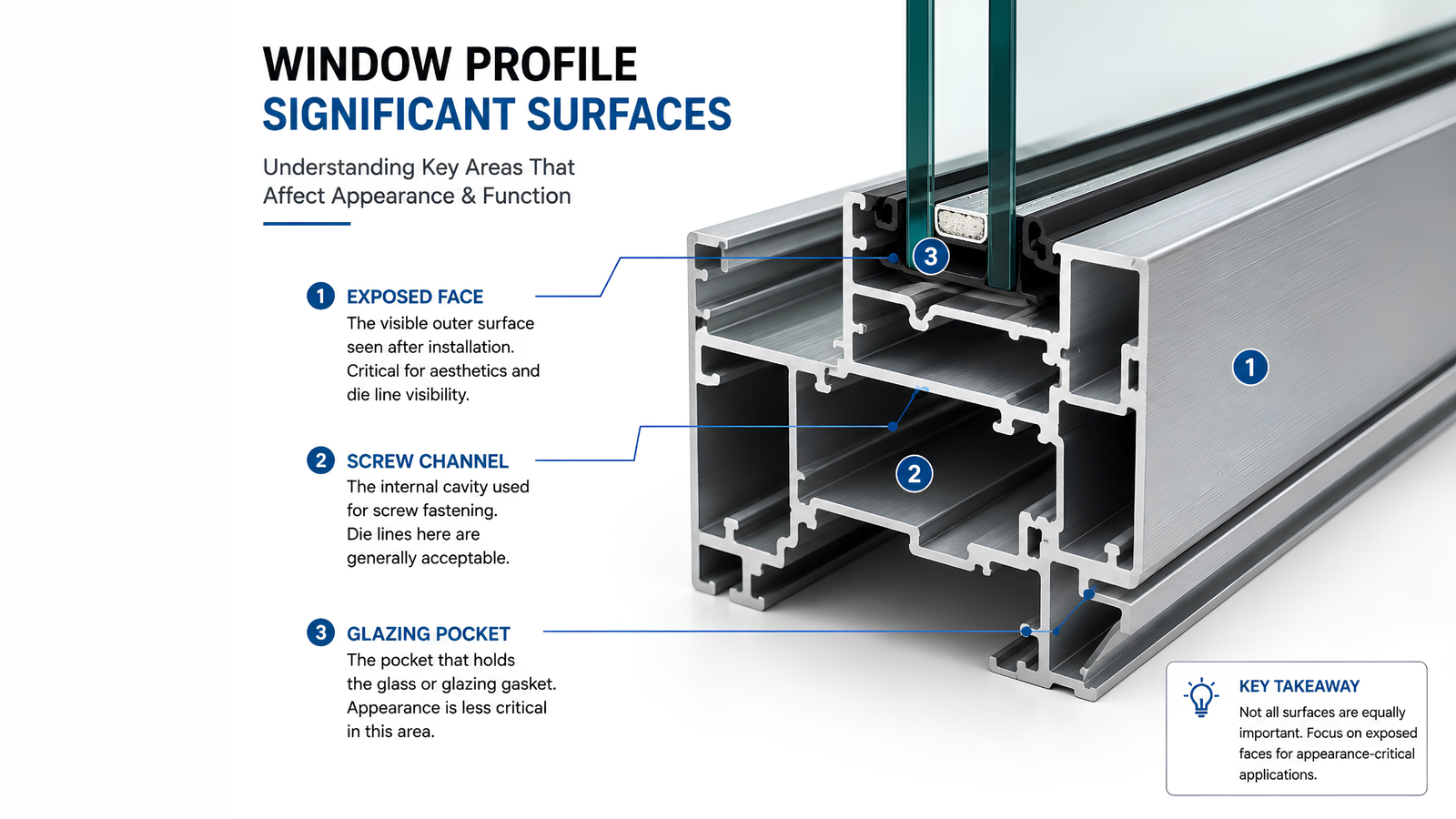
If a die line sits inside a hidden screw channel — nobody sees it after installation, the screw fits correctly, and dimensions are within spec — rejecting the whole extrusion purely for cosmetic reasons on an unseen surface is usually commercially unreasonable, unless the specification explicitly requires that surface to meet a cosmetic standard too.
Move that exact same severity of line to the exposed architectural face, and the decision can flip completely. This is why customer and extruder need to agree, in writing, on:
- Which surfaces are "significant" (visible/exposed after final assembly)
- What the final finish will be
- What visual quality standard applies to each surface
- What reference sample or acceptance limit governs the decision
Without this conversation happening upfront, "is this die line acceptable?" turns into a matter of opinion instead of a specification check.
6. Does EN 755-9 Give a Simple Die-Line Limit?
No — and this trips people up. EN 755-9 governs dimensional and form tolerances (width, wall thickness, straightness, twist, and similar characteristics). It is not a cosmetic acceptance catalogue with a stated die-line depth limit.
Surface quality is governed separately — by the purchase specification, the engineering drawing's significant-surface definition, the required finish, and an agreed visual standard or reference sample.
7. A Practical Inspection Method
When a die line is reported, don't jump straight to accept or reject. Work through this sequence:
- Check direction. Parallel to extrusion direction? Continue investigating a die/process source.
- Check location. Measure distance from an edge, rib, or reference feature.
- Inspect consecutive lengths. Same position repeatedly points to die/process source.
- Careful tactile check. Can it be felt with a fingernail? A pronounced physical groove deserves closer investigation — but this isn't a calibrated acceptance test on its own.
- Inspect under controlled lighting. Rotate the profile relative to the light; some optical streaks only show at certain angles.
- Check the significant surface. Is this face actually visible in the finished product?
- Check the final surface treatment. Mill finish, anodized, powder coated, or machined?
- Compare against a reference sample or written spec — far stronger evidence than "looks okay to me."
- Inspect die bearing and production history. Polishing condition, damage, nitriding status, temperature/speed history.
- Separate die line from pickup and streaking before deciding on corrective action — the fix is different for each.
8. Shop-Floor Diagnostic Matrix
| Observation | Investigate |
|---|---|
| Continuous line, same position every length | Die bearing / die line |
| Short intermittent score marks | Pickup |
| Random line, changing position | Handling / scratch |
| Dark/light band after anodizing | Streaking / microstructure / etching response |
| Line near a thickness transition | Metal flow / local die-design influence |
| Line worsens with press speed | Process temperature / die-interface condition |
| Appears after a long die-running campaign | Bearing deterioration / adhesion / pickup |
| Same mark on every cavity | Common process/material factor |
| Mark only on one cavity | Cavity-specific die condition |
This matrix points toward root-cause direction — it isn't an automatic defect classification.
9. Why Anodizing Raises the Stakes
For mill-finish industrial profiles, fine die lines usually don't matter. For clear anodized architectural profiles, surface consistency becomes critical — and here's why: during pretreatment and etching, the surface is chemically attacked, and different microstructural regions can respond to that attack differently, producing visible imperfections. Existing die lines and pickup marks may also survive etching and remain visible afterward.
That's why the same geometry intended for clear anodizing on an architectural face may need tighter surface control at the die and process level than an identical profile destined for powder coating in a hidden industrial assembly.
10. Can Powder Coating Hide Die Lines?
Sometimes — but never assume it will.
Powder coating adds a coating layer and changes the visual surface. Fine extrusion texture often becomes less noticeable. But a pronounced groove, pickup mark, or rough patch can still telegraph through the coating and remain visible.
11. What Should the Die Correction Team Check?
Once a die-line problem is confirmed, the correction team should map the exact profile location back to the corresponding position on the die, then inspect:
- Bearing surface and bearing edge condition
- Local polishing condition
- Evidence of aluminium adhesion
- Damaged nitrided areas
- Foreign particles at the bearing
- Bearing transition zones
- Prior correction marks
Depending on the actual root cause identified, corrective action may include:
- Cleaning the bearing
- Removing adhered aluminium
- Careful, targeted bearing polishing
- Correcting a specific local bearing condition
- Reviewing nitriding condition
- Reviewing extrusion temperature and reducing speed
- Checking billet quality and homogenisation
- Reviewing die design and metal flow balance
12. A Practical Internal Classification System
Instead of a binary OK/NOT OK call, many extrusion companies benefit from a simple internal surface grading system:
| Grade | Typical use | Requirement |
|---|---|---|
| Grade A — Premium cosmetic | Clear anodized architectural, decorative exposed components | Very high surface consistency, tightly controlled die lines/streaking |
| Grade B — Standard visible | Powder-coated windows/doors, normal architectural components | Minor process texture accepted if final appearance meets agreed visual standard |
| Grade C — Functional | Structural profiles, hidden sections, machine frames | Appearance secondary unless it affects function, dimensions or fabrication |
This is not an EN 755 classification — it's an example internal framework. Companies should define their own measurable inspection conditions and get customer sign-off on the standard, ideally backed by an approved reference sample.
13. The Best Way to Avoid Customer-Extruder Arguments
A specification that simply says "surface should be good" is close to useless in a dispute. A specification worth having instead defines:
| Surface application | Architectural / industrial / decorative |
| Final finish | Mill finish / anodized / powder coated / polished |
| Significant surfaces | Marked directly on the profile drawing |
| Inspection condition | Agreed lighting, viewing distance and orientation |
| Acceptance criteria | Written internal/customer specification |
| Reference | Approved limit sample where appropriate |
With this in place, the conversation shifts from "I think this is a defect" to "does this profile meet the agreed surface-quality requirement?" — a far more professional and far faster discussion to resolve.
Final Understanding
Die lines are longitudinal surface features that come from the interaction between hot aluminium and the die bearing. But not every visible extrusion line is a rejectable defect. Fine, process-related texture may be entirely acceptable on one application and completely unacceptable on a premium clear-anodized architectural face carrying the same severity of line.
The simplest way to remember it: the die line describes what you see. The specification decides whether you reject it.
References & Further Reading
- Aluminum Extruders Council — Extrusion Finishes & Fabrication guidance (aec.org)
- QUALANOD — Anodizing Defects Catalogue (defects.qualanod.net)
- Product Defects in Aluminum Extrusion and Their Impact on Operational Cost — technical paper, King Fahd University of Petroleum & Minerals
- EN 755-9 — Aluminium and aluminium alloys, extruded rod/bar, tube and profiles — Tolerances on dimensions and form