

Put an aluminium profile on a granite table and watch one corner lift off the surface. Ask five people on the shop floor what's wrong, and you'll often get the same answer: "it's twisted." Sometimes that's correct. Often, it isn't.
Straightness and twist can produce a very similar symptom — a profile that won't sit flat, a gap under one corner, a part that looks "bent." But they are two completely different types of deformation, with different causes and different fixes. Confusing them is one of the most common — and most costly — mistakes in extrusion quality troubleshooting.
The Core Idea: Path vs Orientation
Picture a perfectly extruded profile fresh out of the die. Every cross-section along its length has the exact same position and the exact same orientation. Now, two fundamentally different things can go wrong from there:
The cross-section can progressively rotate along the length — that's a twist problem.
Everything else in this article builds on that one distinction, so it's worth reading that highlighted box twice before moving on.
1. What Is Straightness?
Straightness answers a simple question: does the extrusion travel in a straight line along its length? The cross-section itself doesn't necessarily rotate — it's the longitudinal path that curves, like a road that bends instead of running straight. On the shop floor this is commonly called bow, bend, or sweep, though terminology varies by company and by which standard governs the order.
A useful way to picture it: imagine a 6-metre extrusion laid against an imaginary perfectly straight reference line. At the worst point along its length, the profile sits, say, 4 mm away from that line. That 4 mm gap — measured under the specified method — is the straightness deviation.
One detail that trips up a lot of inspection routines: straightness may need to be checked in more than one orientation. A profile can look perfectly straight viewed from the top and still show a clear bow viewed from the side — this is especially relevant for wide, thin, or asymmetric sections, where deviation in one plane can be easy to miss if you only check one.
2. What Is Twist?
Now set bending aside completely. Imagine the centre path of the profile is perfectly straight — but the cross-section slowly rotates as you move along its length. That progressive angular rotation, independent of whether the path itself is straight, is twist.
A simple way to feel the difference: hold a long strip of stiff material flat at one end, then rotate the far end without moving it up or down. The strip's overall direction hasn't changed — it isn't bending toward or away from you — but its cross-section is rotating around the length axis the whole way along. That rotation, and nothing about the path, is what twist measures.
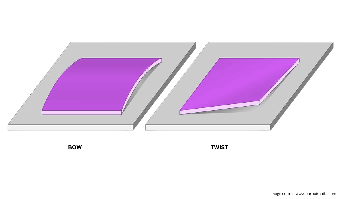
The Engineering Difference, Side by Side
| Straightness | Twist |
|---|---|
| Profile path changes | Cross-section orientation changes |
| Longitudinal bending | Longitudinal rotation |
| Think: bow | Think: torsion |
| Deviation from a straight reference line | Rotation accumulated along profile length |
| Centre path curves | Centre path can remain straight |
| Usually expressed in mm deviation | Expressed as angular or equivalent linear deviation, per standard |
The Table Test — And Why It Can Mislead You
Here's the practical question that causes most of the confusion: you put a profile on a granite table and one corner lifts by 5 mm. Is that twist?
That 5 mm gap could come from straightness deviation alone (the profile bows, so one end naturally lifts even with zero rotation), from twist alone, or from a combination of both acting together. A visual check can't tell you which.
This is exactly why formal measurement practice treats the two separately. Common tolerance guidance describes measuring twist by resting the profile on a flat surface, measuring the maximum gap at any point, and then subtracting the profile's already-measured straightness deviation from that gap — what remains after subtraction is the actual twist value.
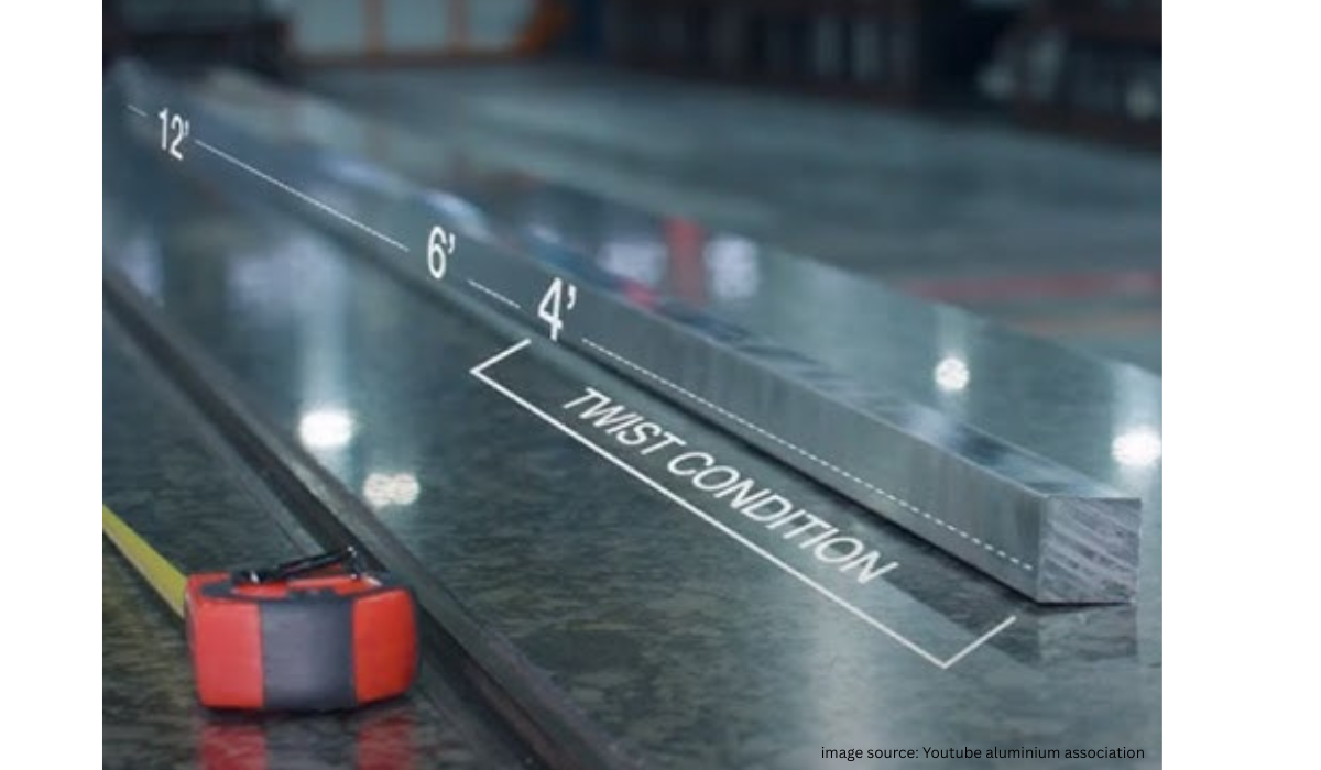
The Cleanest Way to See the Difference: Track the Cross-Section
If you want a mental model that never fails, imagine slicing the extrusion every 1 metre and looking at each cross-section in sequence.
A profile with no defect: every slice sits in the same position, facing the same direction.
A profile with straightness deviation: each slice's position shifts sideways from the one before it — but the orientation stays essentially the same. The cross-sections are translating away from the straight path.
A profile with twist: each slice's position may stay roughly on the same path — but its orientation rotates a little more than the slice before it. The cross-sections are rotating.
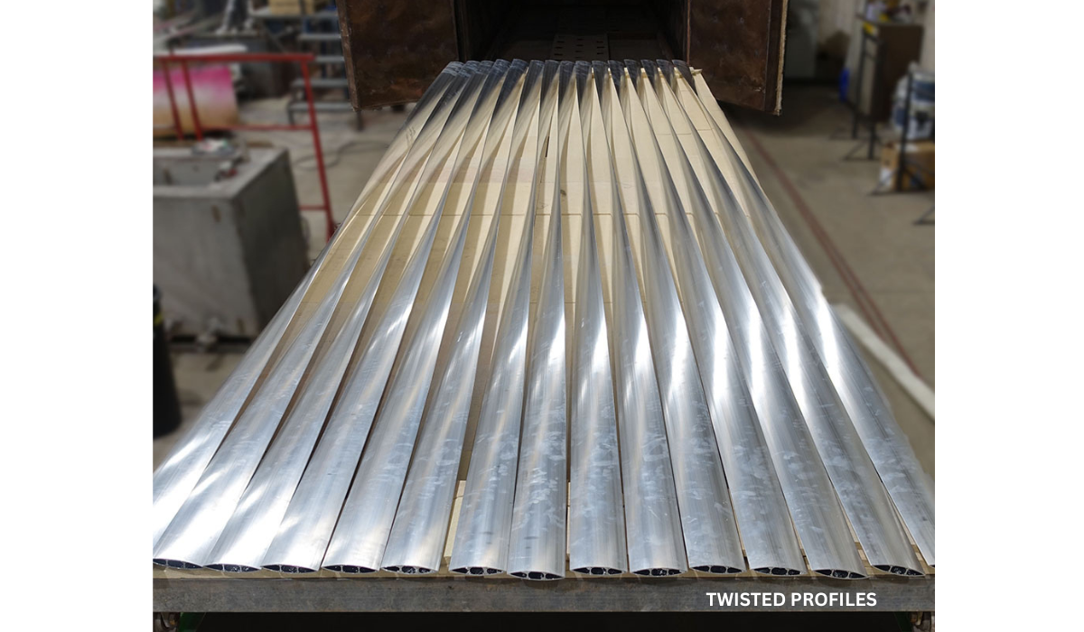
Twist = rotation of the cross-section along the profile's length.
Why Does Straightness Deviation Occur?
The underlying mechanism is almost always some form of imbalance. The main contributors:
Uneven metal flow at the die exit
If one side of a profile exits the die faster than the other, the faster side effectively tries to advance ahead while the slower side holds back — and the profile curves as a result. A straightness problem can genuinely begin as a metal-flow balance issue inside the die, which is why die correction is often the first place to look.
Uneven cooling
If one side of the extrusion cools faster than the other, the two sides contract under different thermal histories, and differential shrinkage pulls the profile out of straight. Fan direction, blocked nozzles, water distribution, air-water balance, profile orientation on the runout table, and thick-to-thin section cooling differences are all worth checking. Cooling uniformity isn't just about achieving the right mechanical properties — it's a dimensional-control parameter too.
Puller misalignment or uneven pulling influence
The hot profile has relatively low resistance to deformation compared with the finished, aged product. If the puller guides it even slightly off the intended path, that low resistance means the deviation can set in easily. Don't send every straightness complaint straight to the die shop — check runout and puller alignment first.
Poor runout table support
Thin, wide, or long-legged profiles at high temperature are especially sensitive to gravity and handling if support along the runout table is inadequate.
Improper stretching
Stretching after cooling is meant to straighten the extrusion and contribute to work hardening — but poor gripping, unequal alignment, incorrect orientation, or over/under-stretching can all leave the final geometry out of tolerance, even when the process looked fine at the time.
Why Does Twist Occur?
Twist is usually the more complex flow-and-thermal problem of the two. Key contributors:
Rotational metal-flow imbalance
Straightness-causing flow imbalance tends to be roughly linear — one side fast, the other slow. Twist-causing imbalance is different: it's imbalance arranged in a rotational pattern around the profile — for example, opposite corners running fast while the other two corners run slow. That pattern creates a genuine rotational tendency as the profile exits the die, rather than a simple side-to-side push.
Asymmetric profile geometry
Compare a symmetrical box section with an L-shaped profile. The L section has an uneven distribution of metal — different wall thickness, local mass, heat retention, die resistance, and cooling behaviour in different areas. The more asymmetric the geometry, the harder flow and thermal balancing becomes, and the more twist-prone the profile tends to be.
Uneven quenching across the profile's width
If one side of a wide profile receives more cooling than the other, the two sides contract differently. When that thermal imbalance is distributed unevenly across both the width and the geometry (rather than simply front-to-back), the resulting distortion can become genuinely rotational rather than a simple bow.
Incorrect profile orientation during cooling
Rotating how an asymmetric profile is oriented on the runout table changes its exposure to air or water cooling, its gravitational behaviour, and its support contact conditions — all of which can influence whether distortion shows up as bow, twist, or both. For difficult profiles, orientation should be treated as a deliberate process condition, not an incidental detail.
Stretching a profile that's already twisted
Longitudinal stretching applies force primarily along the length of the profile. It can meaningfully improve straightness — but it does not automatically remove rotational error. This explains a common shop-floor observation: "the profile got straighter after stretching, but it's still twisted." That's expected, because straightness and twist are genuinely different deformation modes that don't respond to the same corrective action.
Straightness and Twist Can Exist Together
This is one of the most important practical points in the whole topic. A profile can be:
- Straight but twisted — the path follows a straight line, but the cross-section rotates progressively along the length.
- Bent but not twisted — the path curves, but every cross-section keeps the same orientation.
- Both bent and twisted — the path curves and the orientation rotates, which is entirely possible in real production.
This is exactly why relevant tolerance standards treat straightness and twist as separate form-tolerance characteristics rather than one combined "bentness" score — under EN 755-9, for instance, straightness and twist sit in separate clauses within the standard's form-tolerance section. And it's exactly why relying on a single visual check — "does it sit flat on the table?" — isn't enough to diagnose which problem you actually have.
A Note on Measurement Standards
Different tolerance systems define and measure these characteristics somewhat differently. European practice under EN 755-9 evaluates straightness as deviation from a straight line along the profile's length, and separately evaluates twist by resting the profile on a flat base plate under its own weight and measuring the maximum gap, expressed against tolerance tables based on profile width and length. North American tolerance references follow a broadly similar flat-surface twist measurement, explicitly subtracting the measured straightness deviation from the flat-surface gap to isolate the twist component.
Practical Shop-Floor Diagnosis Sequence
When a dimensional-form complaint comes in, this sequence gives you a reliable path to the root cause rather than a guess:
| Question | What it tells you |
|---|---|
| Is the profile's centre path curving? | Suspect straightness / bow |
| Is the cross-section orientation changing end to end? | Suspect twist |
| Does the gap disappear when re-oriented on the table? | Investigate self-weight, support and measurement setup |
| Does every bar bend the same direction? | Investigate die flow, cooling pattern, puller/runout alignment |
| Does the distortion direction rotate along the length? | Strong evidence of twist |
| Good after stretching but bad after ageing/fabrication? | Investigate residual stress and cooling history |
| One cavity affected but not another? | Investigate cavity-specific flow, bearing condition, die behaviour |
This sequence isn't a replacement for the applicable standard — it's a root-cause thinking method to run before you reach for the tolerance tables.
The Simplest Way to Remember It
If you train a new engineer or operator on nothing else about this topic, this is the version worth remembering:
Twist asks: "Is the extrusion's cross-section facing the same direction throughout its length?"
Or shorter still — straightness is a path problem, twist is a rotation problem.
The same underlying process imbalance — flow, cooling, handling — can sometimes contribute to both at once, which is exactly why they get confused so often. But they are independent characteristics with independent causes, independent measurement methods, and independent fixes. Diagnosing which one you're actually looking at is the first real step toward correcting it.